How To Test Temp Sensor With Multimeter
How to test a faulty thermocouple or resistance thermometer?
The commencement indication that a thermocouple or pt100 sensor is not working correctly will be from the instrument it is connected to. The readings might appear lower or higher than expected or the instrument will be showing an mistake lawmaking.
Instruments connected to a thermocouple or pt100 will often
exist a temperature controller or a readout.
Different errors on a controller volition mean different things depending on the brand and model. Check your temperature controller manual to make sure it isn't an error with the controller itself.
Check if the -ve and +ve leads swapped
If your temperature sensor is a resistance thermometer swapping the -ve and +ve leads will not influence the reading.
Thermocouple readings practise change if leads are not correctly continued.
If -ve and +ve leads are swapped betwixt a thermocouple and an instrument then the reading volition change relative to the ambience temperature e.g. a reading of 100°C with an ambient temperature of 25°C will read as 75°C, if the leads are non correctly connected. Ensure that the -ve thermocouple lead and +ve thermocouple lead are wired correctly to your instrument.
Check for whatsoever thermocouple cablevision wiring issues
Incorrectly wired compensating cable
Incorrect wiring of thermocouple cables tin exist further complicated because thermocouples frequently utilize compensating cable. It is possible that the compensating cablevision is incorrectly wired to the thermocouple. It may appear correctly wired at the musical instrument but not correct between the thermocouple and compensating cable. To avoid this, brand sure -ve and +ve legs match correctly forth the full length of the thermocouple, to the compensating cable, to the instrument.
Using the wrong compensating blazon
Each compensating cable is also tied to a specific thermocouple type. To ensure accurateness yous must only use compensating cable of the same type e.g. a blazon Chiliad thermocouple could only be extended with type k compensating cable. Sometimes other types of cable such equally general instrument cable, or copper cable is used to extend thermocouples and this also creates errors.
Using compensating cable in high temperature environments
The last quirk with compensating cable is that it should not be used in high temperature environments. Thermocouple compensating cable is rated for a lower temperature than thermocouple cable. Try to utilise compensating cable in ambient temperatures to reduce errors.
Check for local heat source bug
If your thermocouple is reading high, it could be because your sensor is located also close to a heat source. If your sensor is nearly a local heat source it could increase the temperature being measured as opposed to the position you wish to mensurate temperature.
Check Temperature Transmitter Settings
If your sensor is using a temperature transmitter it is of import to check that the output of the transmitter and the input of the instrument is the same. Virtually commonly a betoken range of 4…xx mA is used.
Check temperature controller settings
Check input settings on temperature controller
For case, if you have your temperature controller setup for Blazon S input merely adhere a Type B thermocouple sensor it would display an incorrect temperature and lead you to believe your sensor was faulty. Yous will need to make sure the input selected on the controller matches the blazon of thermocouple or resistance thermometer continued to it.
There are also a couple of controller errors that point to a fault in the temperature sensor.
Instrument shows: Input signal higher or lower than limit (Out of range fault)
The controller could exist displaying several things indicating that it believes in that location is an out of range error. Common brands of controller could show:
| Brand | Indicate below limit | Signal above limit |
| Vertex | uuuu | nnnn |
| BTC Brainchild | LLEr | HLEr |
| Eurotherm | LLLL | HHHH |
| Yokogawa | uuuu | oooo |
Each brand and model of controller is unlike so look in your temperature controller manual to observe out how an out of range error will show on your specific model.
If you have an out of range mistake the input the temperature sensor is providing is out of the expected range according to the configured input on the controller.
For instance, if you had your controller setup for Blazon South thermocouple input it would expect a small range of mV. If you then connected a Type Due east thermocouple, a thermocouple with a much higher mV range, at 300°C it would testify an out of range error.
Instrument shows: Sensor Break Fault (Open Circuit)
If the controller shows an open circuit error the connection to the sensor is not complete. This could mean either i of the sensor terminals is not connected to the controller or there is a break somewhere in the sensor.
Common brands of controller could evidence:
| Brand | Sensor Break Error |
|---|---|
| Vertex | open |
| BTC Brainchild | SbEr |
| Eurotherm | Sbr |
| Yokogawa | —- |
Each make and model of controller is different so look in your temperature controller manual to find out how a sensor break error will prove on your specific model.
If you have checked that the sensor is properly connected to the controller and you lot nevertheless get an open excursion error y'all will need to disconnect the sensor and remove it from your process to further test the broken thermocouple or broken thermometer for faults.
Acquit a visual check of the temperature sensor
After removing the sensors from your process, visually check for damage along the length of the sheath and at the measuring point. On a thermocouple you lot will have a measuring junction at the tip, on a resistance thermometer you volition take an element at the tip e.g. a pt100 chemical element.
If there are any breaks along the sheath or the tip of the sensor is broken it will probably exist the cause of the mistake. If visually goose egg appears to exist wrong, you can verify any internal breaks with a multimeter.
Troubleshooting temperature sensors with a multimeter
In-head thermocouple multimeter check
One check you lot tin can bear out with a thermocouple is if you short the +ve and -ve wires in a final connectedness head, if the instrument and whatsoever compensating cables are setup correctly the instrument will give an ambient reading.
Testing a faulty thermocouple with a multimeter
Get your faulty thermocouple and a multimeter.
Alter your multimeter to Continuity beeper/diode symbol/flow of current. Some multimeters will beep if there is a pause in the circuit, some multimeters will beep when the circuit is complete. Know how your multimeter functions.
Diode Symbol:![]()
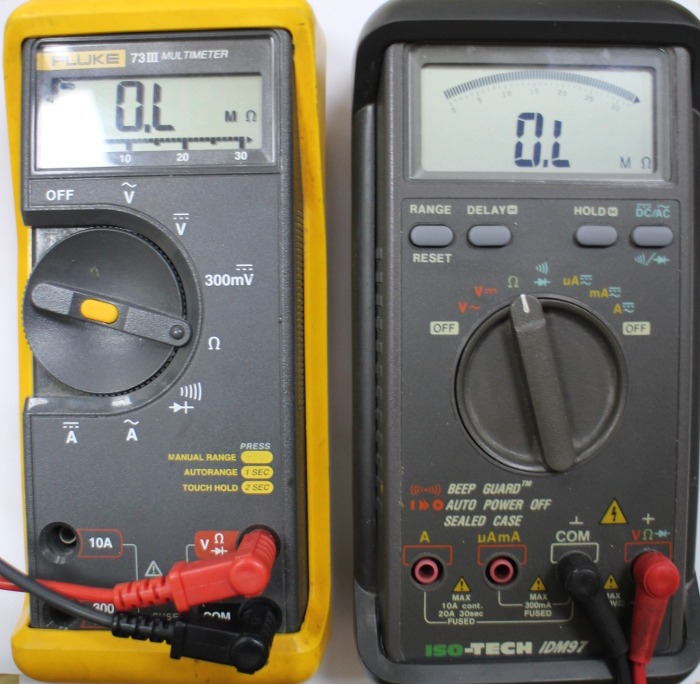
Two multimeters showing the diode/continuity beeper setting selected:
Attach each leg of the thermocouple to the multimeter. It doesn't matter which manner the positive and negative leg are.
Later on connecting the thermocouple to the multimeter a working thermocouple will produce a beep (or no beep if your multimeter works the opposite way). The screen will display resistance in Ohms, which could be zero. If there is a pause it will brandish OL or similar.
If you are experiencing intermittent thermocouple failure you can adjust the position of the sensor and its leads to run into if you can trigger the fault.
Testing a faulty resistance thermometer with a multimeter
In this section, we volition explain how to examination RTD with a multimeter. So, after removing the faulty resistance thermometer, get your multimeter and change it to the Ohms setting (Ω).
Two multimeters showing the ohms (Ω) setting selected:
Next connect the resistance thermometer to your multimeter. Information technology doesn't affair which style effectually the positive and negative legs are. Some resistance thermometers have 3 or 4 wires. Brand sure you connect the wires of a similar colour together. E.g White and white connect to one final and red and reddish connect to the other terminal.
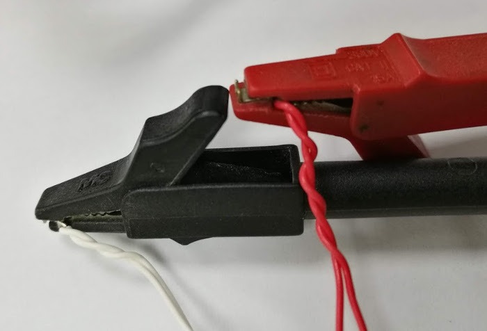
Iv wire resistance thermometer connected to multimeter clips. Showing white-white and red-red leads connected together:
If your resistance thermometer is connected to the multimeter and information technology is reading OL there is a possible suspension in the sensor. You can move any flexible cablevision or tails around to try and trigger any intermittent faults. In a working resistance thermometer, the multimeter would read an ohms value, an example tabular array is beneath:
| Ohms reading at Room Temperature (xx-25°C) | Resistance Thermometer Blazon |
|---|---|
| 107.793-109.735Ω | Pt100 |
| 538.967-548.673 Ω | Pt500 |
| 1077.935-1097.347Ω | Pt1000 |
| ~0Ω | Broken sensor or not a resistance thermometer |
Tolerance to these values would depend on the accurateness of your resistance thermometer and the bodily temperature in your room.
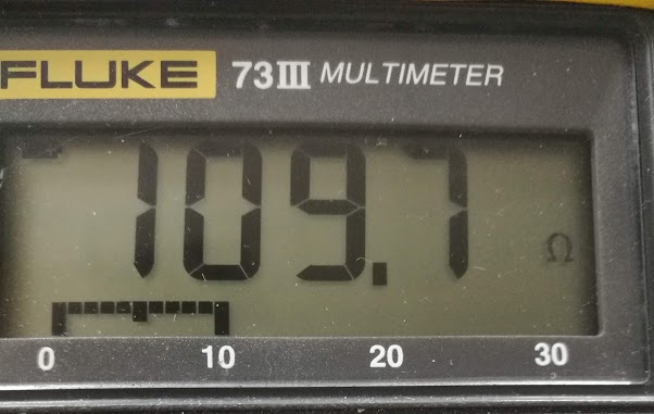
Sample resistance thermometer reading 109.seven ohms which is around 25°C:
Contact Peak Sensors
The above guide is aimed at helping you place problems with your resistance thermometers and thermocouples. Meridian Sensors are experts in temperature sensors and a shortcut to solving your RTD or thermocouple bug is to contact united states of america. We can help solve your temperature sensor bug and either repair or industry replacement sensors.
Call us: 01246 261999
Email us: websales@peaksensors.com
Source: https://peaksensors.co.uk/blog/check-a-faulty-temperature-sensor/


0 Response to "How To Test Temp Sensor With Multimeter"
Post a Comment